ArcFM Water Pressure System Tracing
ArcFM has a mature set of capabilities for representing water distribution networks with multiple pressure zones. And for many situations the out-of-the-box configuration that comes with the Schneiderville database will readily meet your needs. However, ArcFM was created as a configurable application for a reason — one of which is that all situations don’t conform to the standard.
This post discusses a case where you may want to take advantage of that configurability.
The condition we’ll address is devices that are considered to be pressure system boundaries. In terms of ArcFM functionality the Water Pressure System Trace will traverse all equipment considered to be part of the same pressure system as bounded by devices configured to be barriers.
Here’s an example.
Below is a station with pumps, system valves and check valves, with pumps forming the boundary between the 40 PSI (Green) and 60 PSI (Blue) systems. At the right are the results of an ArcFM Pressure System trace initiated on the 40 PSI system – just as we would expect. Great!
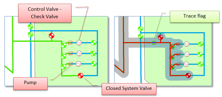
Within the standard configuration devices that are considered pressure system boundaries are:
Regulators – classes with the REGULATOR model name
Closed valves – classes with the VALVE model name and a field with the model name NORMALPOSITION that has a value of[0] Closed.
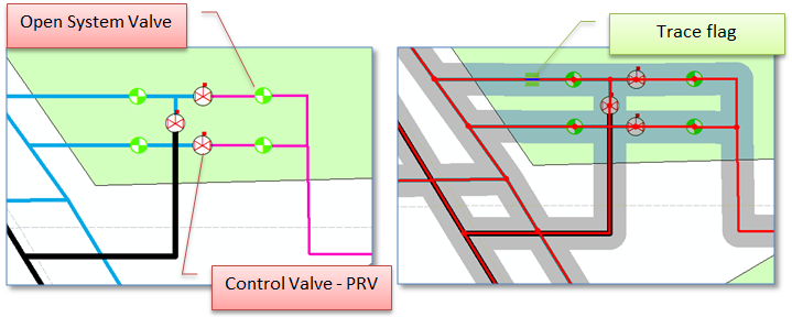
Say, however, you have pressure reducing valves defined as a subtype of your wControlValve feature class that act (in the field) as pressure system boundaries? The class has the VALVE subtype, but they’re not ‘closed’ and we don’t want them to be closed, because they’re not. They don’t stop flow of water but rather ‘regulate’ it to a set pressure safe for use in the lower pressure system. All this said when we perform an ArcFM Pressure System trace at a station with our pressure reducing valves we get unexpected (and undesired) results – as seen below.
So, are we stuck? Do we need to change out data model? Do we need to change our data? No, to all of these. We just need to take advantage of some of the ArcFM configurability we mentioned at the beginning. Here are some configuration changes we can apply to change things:
• Add the class model name REGULATOR to our control valve feature class
• Remove the class model name VALVE from our control valve feature class
• Add fields SOPIN and SOPOUT to our control valve feature class and assign the SOPIN and SOPOUT field model names to the fields respectively (note that these fields simply need to be present, they don’t need to have data assigned)
• Assign the “ArcFM Water Regulator Trace Weight” auto-updater to the “On Feature Create” and “On Feature Update” events on the WATERTRACEWEIGHT fields on our control valve feature class
After the changes we do need to change the data a bit – but not through a complex process. The configuration changes we made need to get reflected in the trace weight field (the place where the rubber hits the road with many ArcFM configurations). We just need to jigger the trace weight values – a process that’s described here and here.
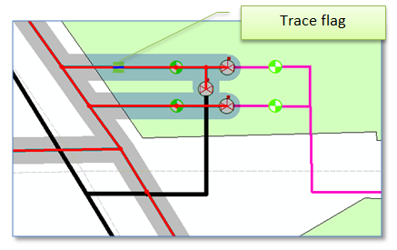
After applying our configuration changes we can re-run the ArcFM Pressure System trace at our station with the PRV’s, and voilà, we get expected results.
Summary
This post has described a specific case demonstrating the value and power of the configurability of the ArcFM solution. In this case we were able to alter configuration of a class containing control valves to act as barriers to a pressure system trace. One of the many capabilities and advantages of a configurable application like ArcFM.