(Is) Breaking Bad?
Breaking geometric network lines, that is.
This is often one of the most significant issues faced when building a new utility geometric network. The question more fully stated is, at what points do you “break” or “split” lines for network (or non-network) equipment and at what point do you simply “connect” equipment to the line without splitting. There is no single answer that fits all companies or all conditions. Also, this is not a decision prescribed by your data model(*). But it’s an important one, and you should be aware of the effects of either course.
(*) The data model defines classes and attributes but the conventions used to create features within that model are established by the application software and, ultimately, by the user.
Fundamentals
Let’s cover some fundamentals first. A geometric network is comprised of junctions (points) and edges (lines). Without going into a lot of detail here, there are two types of network edges; simple and complex. A simple edge can only connect to other edges or junctions at its endpoints. Complex edges can have connections at the endpoints and anywhere along the length of the edge. Here’s a link to the Esri resources that gives the full story. For this study we’re going to assume complex edges – which in our experience are usually used for most utility line features.
Cases where you really need to split lines
We started out by saying there was a choice; to break or not to break. But that’s a bit simplistic. There are cases where a device really needs to break a line. Here are some examples.
- In an electric network any device that can take on an “open” position and thus be fed by different feeders on either side must split an underlying line. As can be seen below ArcFM Feeder Manager will assign a “FeederID” value to each distinct primary line segment. If the open device is simply connected to the line and does not split it then this could lead to an ambiguous condition where the same feeder is displayed on either side of the open. Among other cases where you’d likely require a split would be for phase or wire change locations and step-down transformers.
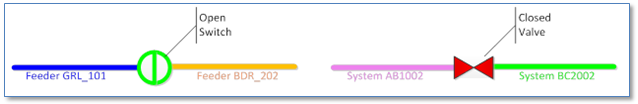
- In a gas or water network a similar condition holds. Any device that can be closed to stop flow of gas or water should typically split the line. This is especially the case if a goal of the GIS is to represent distinct pressure systems and where at least some map displays will be based on the assigned pressure system. Other cases where you’d likely require a split are regulators and pressure monitors.
- In an ArcFM Fiber Manager network any device at which a splice or change in network connectivity can occur must split the line.
There may be other conditions that require a split based on your particular implementation design.
Cases where splitting is optional
There are other cases where, based on your company’s specific business drivers you may choose to split or simply connect. Here are a few examples.
- The connection of a distribution transformer to a primary conductor. The primary wire on either side of the transformer is part of the same feeder, with the same physical properties and is operated at the same voltage – so there is no ArcFM requirement for the primary to be split. Though you can choose to split based on requirements of your engineering analysis system, work management system, asset system or some other requirement. (Note that secondary lines, if mapped, are always as lines distinct from the primary – and typically in a different feature class.)
- The connection of devices that form boundaries between cathodic protection zones. A case in point would be an insulated fitting – unless have a business need to symbolize pipes on cathodic protection zone.
- Fiber optic slack loops and/or transition points. In a fiber network slack loops are typically connected to a fiber cable and do no split it. Transition points (risers) may split the line if you have the requirement to distinguish between overhead and underground cables, but otherwise may not.
Pros and Cons
So, given these are other conditions where any particular implementation may or may not choose to split a network edge, how do you decide what’s right for your company? First, if you have any type of electronic mapping system at all then you’ve likely established some conventions – either intentionally or by default – which you may, or may not want to continue as you move forward into ArcFM. That said, here are a few potential guidelines to think through.
Dataset Size / System Performance
As with any computer data set the more records present the more work the application will have to do to operate on that dataset. When we say “work” this includes things like display, attribute and spatial query, tracing, interfaces, replication and backup. As a simple illustration of the point consider the case of Esri Turbo Layers. By aggregating the geometries of all features in a given rectangle and storing the resulting union in one feature per rectangle map display can, in cases where feasible, be improved dramatically.
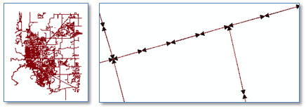
Another, more direct way to evaluate the impact is to perform a simple test of splitting lines in a sample dataset and comparing draw performance using the ArcMap PerfQA Analyzer. Given a dataset of approximately 6,800 street centerlines (left below) we split each line into 4 new lines (right) below. Using identical symbology we found that the split feature class consistently took twice as long to render as the original class.
We’re not suggesting that anyone try to create turbo layers of their utility network classes (typically not feasible), only that splitting edges creates more lines and, when done to excess can impact system performance in noticeable ways. So, all things being equal, from an overall performance standpoint we’d suggest connecting rather than splitting.
Meaningful Segments
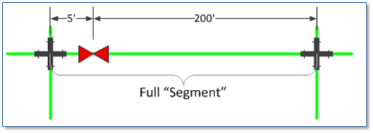
While splitting lines can make the result of some trace operations more intuitive to many users it can also create features that might not correspond to what those same users might consider to be meaningful segments. Consider the example of a water main in a GIS database where most users would consider a “segment” to be a main between junctions, such as the 4-way crosses below, or specialized fittings such as transition fittings, and/or end points. However, when we add the valve that splits the pipe between fittings we end up with a small (5’) segment not often considered separate from the remaining 200’ segment of pipe. Further complicating the matter can be the fact that the valve may in fact be part of the same physical fitting as the cross but separated by a small distance to adhere to mapping conventions.
Of course the same condition can exist in an electric distribution network with lateral fuses offset a small distance along a tap point on a primary line. Potential strategies for dealing with this case include:
- Assigning the length of the small fragment line to the larger line and, optionally, adding a code to the small fragment that it should not be considered for purposes such as reporting or engineering analysis.
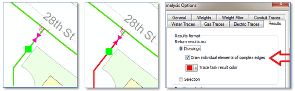
- Not splitting the main at the valve location, but rather connecting the valve to the main. Yes, this contradicts one of the first things we said, but it may be the case that symbolizing the small segment is really not so important. And if the main is not split, you can choose the tracing Analysis Option to “Draw individual elements of complex edges” to have traces return expected results.
Versioning Conflict Resolution
This is a complex consideration and we won’t try to cover all aspects of here, but it’s certainly a condition of which an implementer should be aware. To start, Esri Enterprise Geodatabases support multiple, simultaneous editing sessions by means of a technique called “versioning”. For as much on versioning in general as you’d ever want to read, check out this link.
Now specifically if two users in different versions have updated the same feature, or optionally the same attribute on the same feature, then after the first user has posted her edits when the second user tries to reconcile her version she’ll be informed there is a “conflict” and given options to resolve the conflict. In terms of splitting or connecting a complex edge, regardless of whether both users have performed an edit to split the same line or to connect to the same line either condition will be considered a conflict. There’s no difference up to this point.
There is a difference however when we go to resolve the conflict. Here’s a simple (probably simplistic) description of each case:
- When a change in shape made by connecting two different features to two new vertexes along the edge is found the resolution process examines the geometries and attempts to merge them. (If you’re really curious the process is described here.) We start with the original line, no connections.
![]()
- Then a device is connected to the line first in version A then in version B. After reconciling and posting both the result is a line with a geometry merged from both versions. Connections are maintained to both added devices, regardless of which version the user chooses in conflict resolution.

Why would two users connecting to (not splitting) features to the same feature in different versions cause a conflict? Simply, though it may not seem evident at first, the geometry of the edge is changed by introduction of a vertex at the new point of connection. You may also see a (very) slight difference in the lengths of the lines.
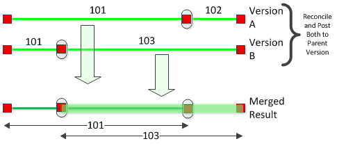
- When a change in shape is made by splitting the line for new features along the course of its geometry the resolution process goes through similar steps, up to a point. We again start with the original line, no connections. (Note that we’re assuming that the ArcMap “Split With Update” behavior is configured. Results with the original split behavior would be different.)
![]()
- Then a device is adding splitting the line in version A and again in a different location in version B. After reconciling and posting both the result is two lines that overlap one another between the added devices. This occurs because when the conflict resolution process attempts to merge involved geometries the temporary result is a line with a self-overlapping segment – which is invalid for geometric network edges – so the final result reverts to two segments that can be merged.
- Ultimately, the user must edit the resulting edges after reconcile to obtain the expected result.
In this particular case, using connections to complex edges offers a simpler solution than splitting.
Summary
Utility geometric networks are composed of lines that carry commodities and devices that control the flow of that commodity through the lines. There are two ways in which a device can be linked to a line; either splitting it forming two new lines or by connecting to it at a vertex along the line. While in some cases the choice of “split” or “connect” is dictated by an application or business requirement, in many cases it is not. Your implementation, and your data migration process should consider both options and adopt the approach that best fits your business needs.