ArcFM Valve Isolation and Pressure Data
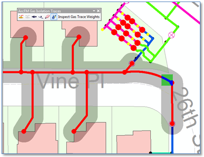
Given an initial “flag” location on a pipe, ArcFM Valve Isolation tracing identifies valves that need to be operated to isolate that location. It also traces to the extent of the area that would be impacted should the identified valves be closed. The way this works, as described in ArcFM Resources, the trace takes a flag location, discovers bounding source(s) feeding the clicked location, discovers other bounding conditions and includes all contained equipment in the result.
Very useful functionality, for sure. Below is an example result.
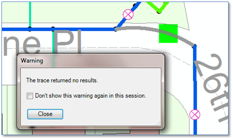
But what if you don’t have a known operating pressure assigned to each pipe segment? In this case you might be presented the message box “Trace Returned No Results,” as shown below.
Clearly in this case the long-term best solution is to obtain correct operating pressures for all of your pipes and update your Geodatabase with that information.
But, as a short term strategy there’s another option. And its viable if you’re at least confident about the location of valves and regulators in your network. The option is this: set up a parallel set of fields with operating pressures as a constant and point the valve isolation tracing at these fields, at least until the time that your actual operating pressure values are complete and correct.
Let’s work through the details.
First, we need to add fields to the DistributionMain class and the RegulatorStation class, as follows:
| Class | New Field | Data Type | Default Value |
| Distribution Main | ArcFMOperatingPressure | Long Integer | 1 |
| RegulatorStation | ArcFMSOPIN | Double | 2.0 |
| RegulatorStation | ArcFMSOPOut | Double | 1.0 |
Now we need to change to field model names the Valve Isolation Trace uses to understand pressure values, as follows:
| Class | Field | Model Name | Action |
| DistributionMain | OperatingPressure | OPERATINGPRESSURE | Remove |
| DistributionMain | ArcFMOperatingPressure | OPERATINGPRESSURE | Add |
| RegulatorStation | SOPIN | SOPIN | Remove |
| RegulatorStation | SOPOUT | SOPOUT | Remove |
| RegulatorStation | ArcFMSOPIN | SOPIN | Add |
| RegulatorStation | ArcFMSOPOUT | SOPOUT | Add |
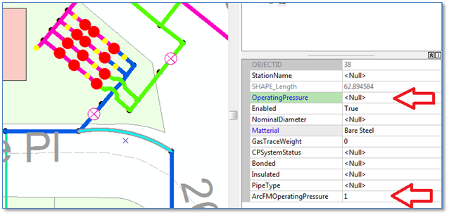
Further, if there is already pipe and regulator feature data in our database, we need to assign default values to our new fields. The easiest way is to use the ArcGIS table Field Calculator tool and set the default value for all existing features for the DistributionMain ArcFMOperatingPressure field and the ArcFMSOPIN and ArcFMSOPOut fields on the RegulatorStation class. As shown below.
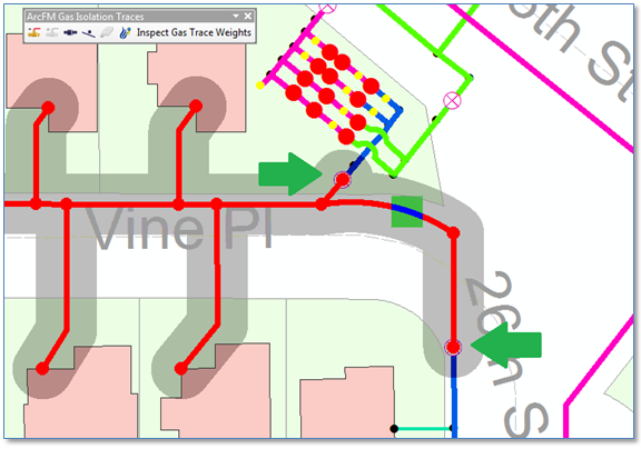
Given that, now we can go back to our pipe segment for which we had an <null> OperatingPressure value. Now we see that the ArcFM Valve Isolation trace gives us expected results. Specifically, it stopped at valves that need to be operated to prevent flow to the flagged location, and includes all pipes and connected equipment that would be affected should those valves be closed.
Summary
If your operating pressure data is incomplete, then by all means the best, long-term course of action is to update it the best, most efficient manner possible. In the meantime, for the purpose of supporting the ArcFM Valve Isolation Tracing function you can simulate expected results by creating new fields and setting your pipe segment operating pressure and regulator inlet and outlet pressures to constants and changing configuration model names to those new fields. When your data is updated, simply change the model names back to the fields with actual data.